Database design
Last updated on 2024-03-26 | Edit this page
Overview
Questions
- What is database design?
Objectives
- Use Entity Relationship Diagrams to visualise and structure your data.
Spreadsheets
In libraries, spreadsheets are often created to keep lists of a variety of things like an inventory of equipment, reference statistics, or items to review for purchase (See What are some of the uses for SQL in libraries?). Spreadsheets, sometimes referred to as tabular data or flat files, are an easy way to display data organized in columns and rows. Column headers describe the data contained in corresponding columns. Each row is a record (sometimes called an observation) with data about it contained in separate column cells.
Spreadsheets can make data gathering easier but they can also lead to messy data. Over time, if you gather enough data in spreadsheets, you will likely end up with inconsistent data (i.e. misformatted, misspelled data).
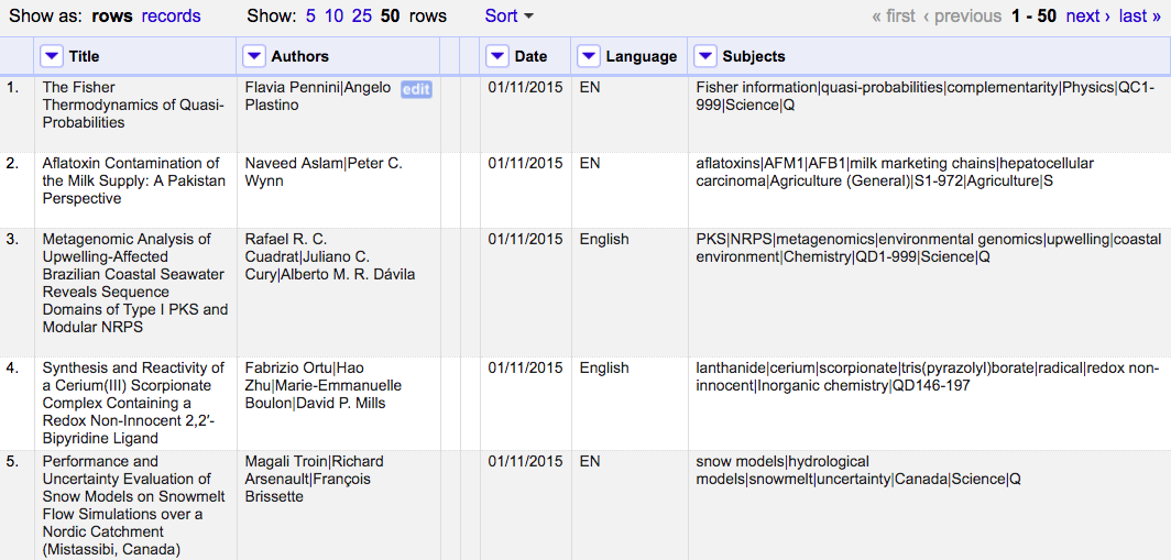
- The data in the “Language” column is formatted in two ways, as an abbreviation and the full word;
- The full names of authors are used, in first name to last name order, with middle name abbreviated, separated by pipes;
- Date format is MM/DD/YYYY and not the commonly used ISO 8601 format;
- The “Subjects” column delimits data by pipes and the data is in a variety of formats such as abbreviations, classifications, and sometimes capitalised. Can you spot anything else?
Designing a relational database for your data can help reduce the places where these errors can be introduced. You can also use SQL queries to find these issues and address them across your entire dataset. Before you can take advantage of all of these tools, you need to design your database.
Database Design
Database design involves a model or plan developed to determine how the data is stored, organized and manipulated. The design addresses what data will be stored, how they will be classified, and the interrelationships between the data across different tables in the database.
Terminology
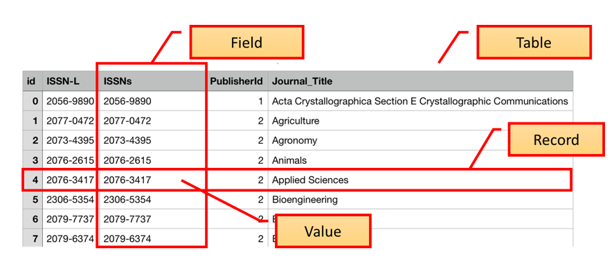
In the Introduction to SQL lesson, we introduced the terms “fields”, “records”, and “values”. These terms are commonly used in databases while the “columns”, “rows”, and “cells” terms are more common in spreadsheets. Fields store a single kind of information (text, integers, etc.) related to one topic (title, author, year), while records are a set of fields containing specific values related to one item in your database (a book, a person, a library).
To design a database, we must first decide what kinds of things we want to represent as tables. A table is the physical manifestation of a kind of “entity”. An entity is the conceptual representation of the thing we want to store information about in the database, with each row containing information about one entity. An entity has “attributes” that describe it, represented as fields. For example, an article or a journal is an entity. Attributes would be things like the article title, or journal ISSN which would appear as fields.
To create relationships between tables later on, it is important to designate one column as a primary key. A primary key, often designated as PK, is one attribute of an entity that distinguishes it from the other entities (or records) in your table. The primary key must be unique for each row for this to work. A common way to create a primary key in a table is to make an ‘id’ field that contains an auto-generated integer that increases by 1 for each new record. This will ensure that your primary key is unique.
It is useful to describe on an abstract level the entities we would like to capture, along with how the different entities are related to each other. We do this using and entity relationship diagram (ER diagram or ERD).
Entity Relationship Diagram (ER Diagram or ERD)
ERDs are helpful tools for visualising and structuring your data more efficiently. They allow you to map relationships between concepts and ultimately construct a relational database. The following is an ERD of the database used in this lesson:
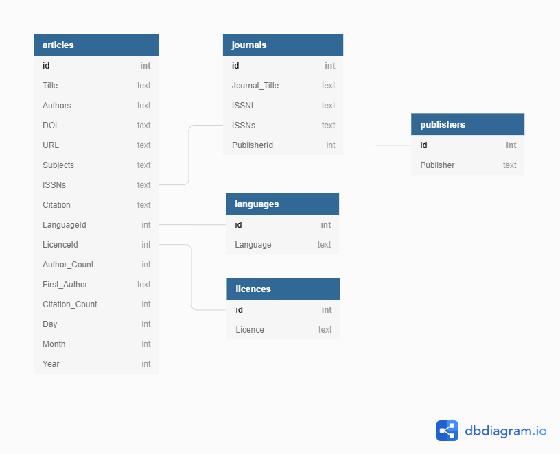
Or you can view the dbdiagram.io interactive version of the ERD.
Relationships between entities and their attributes are represented by lines linking them together. For example, the line linking journals and publishers is interpreted as follows: The ‘journals’ entity is related to the ‘publishers’ entity through the attributes ‘PublisherId’ and ‘id’ respectively.
Conceptually, we know that a journal has only one publisher but a publisher can publish many journals. This is known as a one-to-many relationship. In modeling relationships, we usually assign a unique identifier to the ‘one’ side of the relationship and use that same identifier to refer to that entity on the ‘many’ side. In ‘publishers’ table, the ‘id’ attribute is that unique identifier. We use that same identifier in the ‘journals’ table to refer to an individual publisher. That way, there is an unambiguous way for us to distinguish which journals are associated with which publisher in a way that keeps the integrity of the data (see the Normalisation section below).
More Terminology
The degree of relationship between entities is known as their ‘cardinality’. Using the journals-publishers example, the ‘publishers’ table contains a primary key (PK) called ‘id’. When the PK is used to create a connection between the original table and a different table, it is called a foreign key (FK) in the other table. To follow the example, we see a field in the ‘journal’ table called PublisherID that contains the values from the ‘id’ field in the ‘publisher’ table, connecting the two tables.
There are 4 main types of relationships between tables:
- One to One - each item in the first table has exactly one match in the second table.
- One to Many - each item in the first table is related to many items in the second table, sometimes represented as 1 to * or 1 to ∞
- Many to One - many items in the first table is related to one item in the second table.
- Many to Many - many items in the first table are related to many items in the second table.
In our previous example of the ‘PublisherID’ field in the ‘journals’ table, the ‘publisher’ table has a one to many relationship with the journals table. This is because one publisher may publish many journals, so it will appear multiple times in that field.
A key attribute is often included when designing databases to facilitate joins.
Normalisation
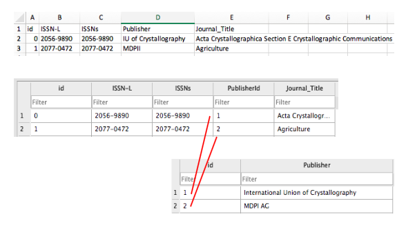
ERDs are helpful in normalising your data which is a process that can be used to create tables and establish relationships between those tables with the goal of eliminating redundancy and inconsistencies in the data.
In the example ERD above, creating a separate table for publishers and linking to it from the journals table via PK and FK identifiers allows us to normalise the data and avoid inconsistencies. If we used one table, we could introduce publisher name errors such as misspellings or alternate names as demonstrated below.
There are a number of normal forms in the normalisation process that can help you reduce redundancy in database tables. Study Tonight features tutorials where you can learn more about them.
Identifying remaining inconsistencies in the ERD
Are there other tables and relationships you can create to further normalise the data and avoid inconsistencies?
For this exercise, you can either use pencil/pen and paper to draw new tables and relationships or use dbdiagram.io to modify the ERD above.
- An ‘authors’ table can be created with a many-to-many relationship with the ‘articles’ table and an associative entity or bridge table between them.
- A ‘subjects’ table can be created with a many-to-many relationship with the ‘articles’ table and a bridge table between them. Can you spot anything else?
Additional database design tutorials to consult from Lucidchart: